

All Products
-
Differential Pressure Gauge
-
Digital Pressure Gauge
-
Stainless Steel Pressure Gauge
-
Precision Pressure Transmitter
-
Programmable Logic Controller
-
Float Level Switch
-
Pneumatic Valve Positioner
-
Temperature Transmitter Sensor
-
Hart Field Communicator
-
Solenoid Valve
-
Control Valves
-
High Accuracy Flow Meter
-
Submersible Water Pump
-
Pressure Transmitter Manifold
-
Ultrasonic Level Meter
-
Voltage Current Power Meter
25kW E2V Control Valves X-Band Magnetron For Marine Radar


| Place of Origin | uk |
|---|---|
| Brand Name | Magnetron |
| Certification | CCC.CE |
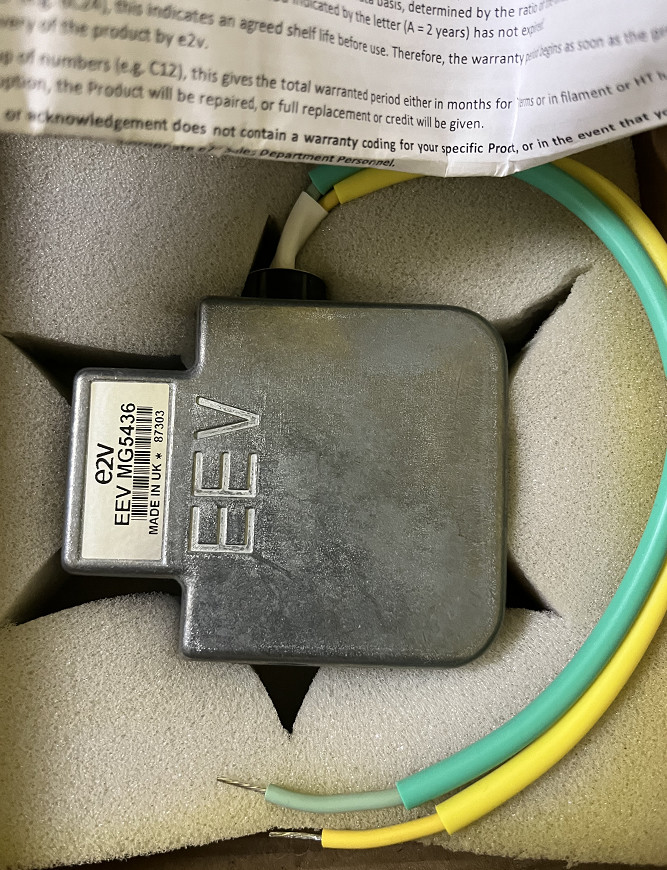
| Model Number | MG5436 |
| Minimum Order Quantity | 1 |
| Price | usd 1050 piece/pieces |
| Packaging Details | carton |
| Delivery Time | 5-8 work days |
| Payment Terms | L/C, D/A, D/P, T/T, Western Union, MoneyGram |
| Supply Ability | 100 |
Product Details
| Product Model | M54365 | Type | Marine Radar |
|---|---|---|---|
| Operating Frequency | 9410 + 30 MHz | Typical Peak Output Power | 25 KW |
| Highlight | Marine Radar Flow Control Valve,Magnetron Hydraulic Control Valve,E2V Hydraulic Motor Control Valve |
||
You can tick the products you need and communicate with us in the message board.
| Cathode | indirectly heated | |
|---|---|---|
| Heater voltage | 6.3 V | |
| Heater current at 6.3 V | 0.5 A | |
| warranty | 1 year |
Product Description
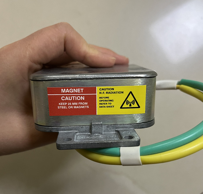
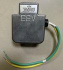
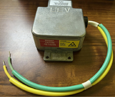
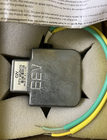
E2V Technologies EEV MG5436 25kW X-Band Magnetron Marine Radar
Description
Electrical
Operating frequency 9410 ± 30 MHz Typical peak output power 25 kW Cathode indirectly heated Heater voltage (see note 1)
6.3 V Heater current at 6.3 V (see note 2)
0.5 A Cathode pre-heating time (minimum) (see note 3)
60 s Input capacitance 9.0 pF max Temperature coefficient of frequency see note 4
Mechanical
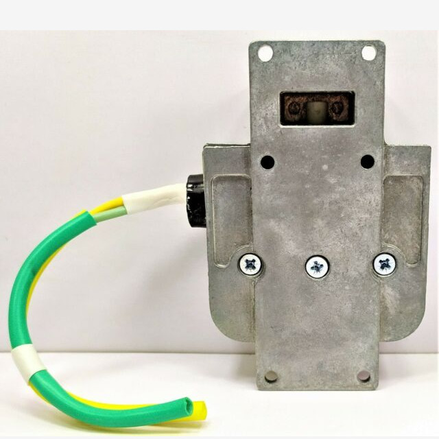
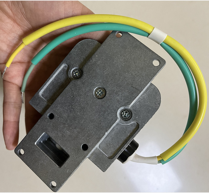
Output no.16 waveguide (22.86 x 10.16 mm internal)
Magnet integral A minimum clearance of 25 mm must be maintained between the magnetron and any magnetic materials.
Coupler IEC UBR100
Cooling natural
Net weight 0.7 kg approx Mounting position any
Compact, rugged, lightweight, fixed frequency pulse magnetron, designed for marine radar applications.
specification
| Brand Name | Magnetron |
| Model | MG5436 |
| Type | Marine Radar |
| Heater voltage | 6.3 V |
| Anode current | 8.0 A |
| Pulse duration | 0.8 ms |
| Output power | 25 kW |
| Output power | 18 W |
| Weight | 0.7 kg approx |
![]()
![]()
![]()
NOTES
1. For optimum performance a value of 6.3 V is recommended. However, this magnetron will work satisfactorily within the specified limits. The magnetron heater must be protected against arcing by the use of a minimum capacitance of 4000 pF shunted across the heater directly at the input terminals; in some cases a capacitance as high as 2 mF may be necessary depending on the equipment design. For further details see the Magnetron Preamble.
2. Measured with heater voltage of 6.3 V and no anode input power, the heater current limits are 0.5 A minimum, 0.6 A maximum.
3. For ambient temperatures above 0 8C. For ambient temperatures between 0 and 755 8C, cathode pre-heating time is 90 seconds minimum.
4. Design test only. The maximum frequency change with anode temperature change (after warming) is 70.25 MHz/8C.
5. The various parameters are related by the following formula: Pi = iapk x vapk x Du where Pi = mean input power in watts iapk = peak anode current in amperes vapk = peak anode voltage in volts and Du = duty cycle. For mean pulse input power greater than 45 W the heater voltage must be reduced within 3 seconds after the application of HT according to the following schedule: Vh = 0.08 (110 7 Pi) volts where Pi = mean input power in watts.
6. Defined as the steepest tangent to the leading edge of the voltage pulse above 80% amplitude. Any capacitance in the viewing system must not exceed 6.0 pF.
7. The maximum rate of rise of voltage for stable operation depends upon detailed characteristics of the applied pulse and the pulser design. The specified maximum rating applies to typical hard tube pulsers. For minimum starting jitter and optimum operation, the recommended rate of rise of voltage for most line type pulsers is from 60 to 90 kV/ms.
8. Tolerance + 40%.
9. Other frequency ranges can be supplied on request.
10. With the magnetron operating into a VSWR of 1.15:1 over a peak anode current range of 6.0 to 10 A. Pulses are defined as missing when the RF energy level is less than 70% of the normal energy level in a 0.5% frequency range. Missing pulses are expressed as a percentage of the number of input pulses applied during a two minute period of observation.
11. Measurements taken ‘as read’ using suitably calibrated equipment.
Recommended Products