

All Products
-
Differential Pressure Gauge
-
Digital Pressure Gauge
-
Stainless Steel Pressure Gauge
-
Precision Pressure Transmitter
-
Programmable Logic Controller
-
Float Level Switch
-
Pneumatic Valve Positioner
-
Temperature Transmitter Sensor
-
Hart Field Communicator
-
Solenoid Valve
-
Control Valves
-
High Accuracy Flow Meter
-
Submersible Water Pump
-
Pressure Transmitter Manifold
-
Ultrasonic Level Meter
-
Voltage Current Power Meter
Dwyer Low Differential Pressure Switch 10 Psig 15A SPDT 60Hz 15A


| Place of Origin | USA |
|---|---|
| Brand Name | DWYER |
| Certification | CE |
| Model Number | 1823-10-20-40-5 |
| Minimum Order Quantity | 10 |
| Price | USD 105 PIECE |
| Packaging Details | carton |
| Delivery Time | 5-8 days |
| Payment Terms | L/C, D/A, D/P, T/T, Western Union, MoneyGram |
| Supply Ability | 1000 |
Product Details
| Product Name | Low Differential Pressure Switch | Repeatability | ±2% |
|---|---|---|---|
| Electrical Rating | 15 A @ 120-480 VAC, 60 Hz | Temperature Limits | -30 To 180°F (-34 To 82.2°C). 1823-00, -20 To 180°F (-28.9 To 82.2°C). |
| Pressure Limits | 10 Psig (68.95 KPa) | Electrical Rating | 15A @120-480 VAC, 60 Hz. |
| Highlight | Dwyer Low Differential Pressure Switch,Low Differential Pressure Switch 10 Psig,10 Psig oil pressure switch |
||
You can tick the products you need and communicate with us in the message board.
| Service: | Air and non-combustible, compatible gases. | |
|---|---|---|
| Electrical Connections: | 3 screw type, common, normally open and normally closed. | |
| Process Connections: | 1/8" female NPT. | |
| Mounting Orientation: | Diaphragm in vertical position. Consult factory for other position orientations. | |
| Set Point Adjustment: | Screw type inside mounting spud. | |
| Weight: | 1 lb, 5 oz (595 g). | |
| Agency Approvals: | CE, CSA, FM, UL. |
Product Description
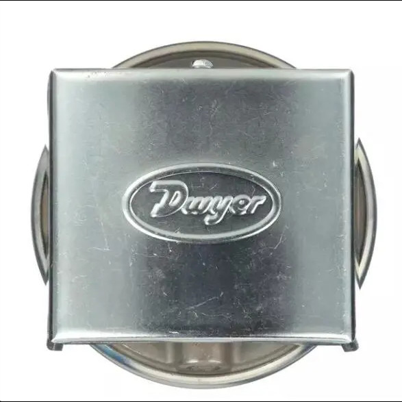
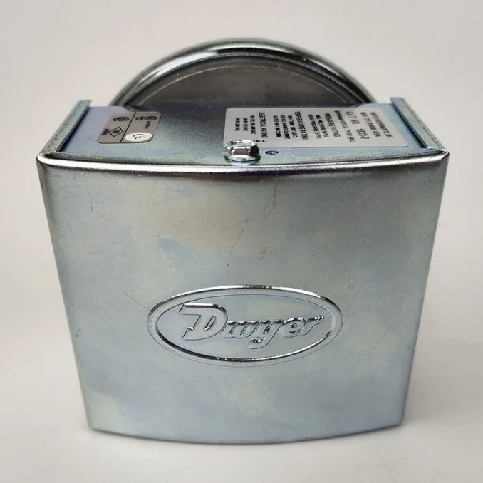
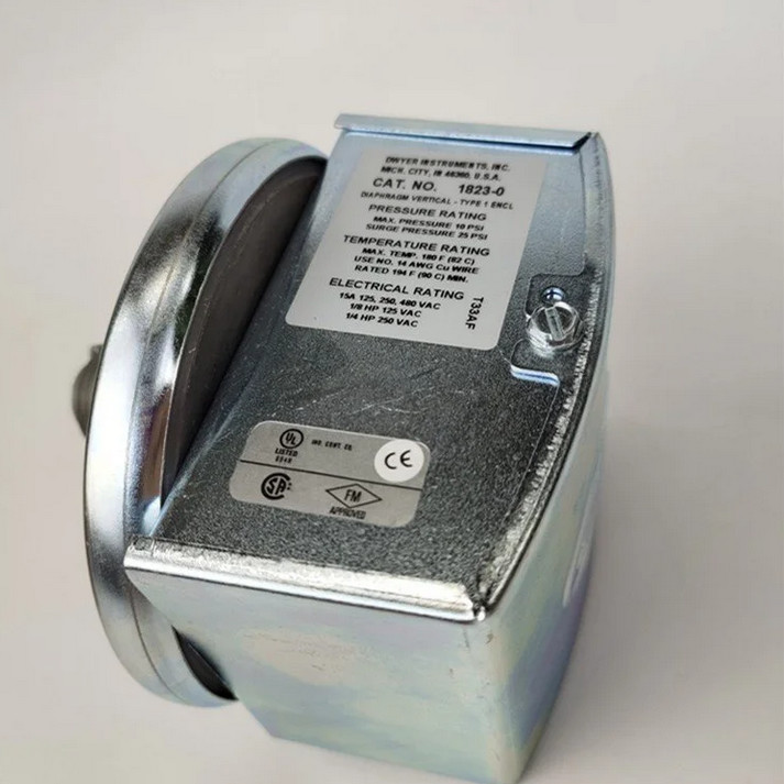
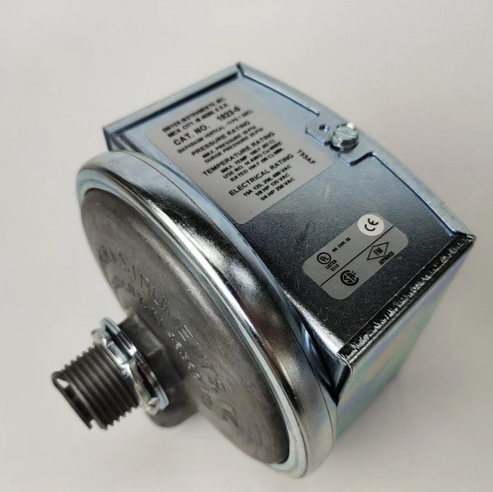
Dwyer 1823-10/-20/-40/-5 LOW DIFFERENTIAL PRESSURE SWITCH 10 psig 15 A 1800 series
Set Points from 0.07" to 85" w.c. Repetitive Accuracy within 2%
Essential for industrial environments, the Series 1800 Low Differential Pressure Switch for general industrial service combines small size and low price with 2% repeatability for all but the most demanding applications. Set point adjustment inside the mounting stud permits mounting the switch on one side of a wall or panel with adjustment easily accessible on the opposite side. UL and CSA listed, and FM approved.
FEATURES
- Compact size and repeatability provide a high-value switch for many industrial applications
- Designed for panel and wall mounting to easily meet mounting requirements in most industrial settings
- Pressure ranges from 0.07 in w.c. to 85 in w.c. make this switch suitable for a wide range of applications
SPECIFICATIONS
| Service | Air and non-combustible, compatible gases |
| Wetted Materials | Consult factory |
| Temperature Limits | -30 to 180°F (-34 to 82.2°C); 1823-00: -20 to 180°F (-28.9 to 82.2°C). |
| Pressure Limits | 10 psig (68.95 kPa) continuous, 25 psig (172.4 kPa) surge. |
| Switch Type | Single-pole double-throw (SPDT). |
| Repeatability | ±2% |
| Electrical Rating | 15A @120-480 VAC, 60 Hz. |
| Process Connection | 1/8˝ female NPT |
![]()
![]()
![]()
DESCRIPTION
Essential for industrial environments, the Series 1800 Low Differential Pressure Switch for General Industrial Service combines small size and low price with 2% repeatability for all but the most demanding applications. Set point adjustment inside the mounting stud permits mounting the switch on one side of a wall or panel with adjustment easily accessible on the opposite side. UL and CSA listed, and FM approved.
![]()
![]()
![]()
APPLICATIONS
Process applications
• Mechanical equipment control
![]()
APPROVALS
- CE Approval
- CSA Approval - Motor Controllers
- CSA Approval - Switches
- FM Approval
- RoHS Letter of Compliance
- UL-Motor Controllers (Components)-Canada
- UL-Motor Controllers (Components)-US
- UL-Motor Controllers-Canada
- UL-Motor Controllers-US
- UL-Switches (Components)-US
ADJUSTMENT
1. If the switch has been factory preset, check the set-point before placing in service to assure it has not shifted in transit.
2. If switching has not been preset or it is desired to change the point, observe the following procedure:
a. To adjust the set point turn the slotted Adjustment Screw clockwise to increase the set point and counterclockwise to decrease the set point.
b. The following is a recommended procedure for calibrating or checking calibration: Use a “T” assembly with three rubber tubing leads, all as short as possible and the entire assembly offering minimum flow restriction. Run one lead to the pressure switch, another to a manometer of known accuracy and appropriate range, and apply pressure through the third tube. Make final approach to the set point slowly. Note the manometer and pressure switch will have different response characteristics due to different internal volumes, lengths of tubing, oil drainage, etc. Be certain switch is checked in position it will assume in use, i.e. vertical, horizontal, etc.
ACCESSORIES MODEL CHART
![]()
INSTALLATION
1. Select a location free form excessive vibration and where oil or water will not drip upon the switch. See special housings for unusual conditions.
2. While not required, positioning the pressure connections down is recommended. Mount the switch with the diaphragm in a vertical plane. Switch with the diaphragm in a vertical plane. Switch must be recalibrated for each change in operating position.
3. Connect switch to source of pressure differential. Metal tubing with 1/4˝ O.D. is recommended but any tubing system which will not restrict the air flow is satisfactory. Note that the low pressure connection may be made to the 1/2˝ spud at the back of the switch if desired. If so connected, drill 1/16˝ diameter holes in the Spring Retainer flange and the head of Adjustment Screw to provide opening to the switch interior and plug the other low pressure connection.
4. Electrical connections to the standard single pole, double throw snap switch are provided by means of screw terminals marked “common”, “norm open”, and “norm closed”. The normally open contacts close and the normally closed contact open when pressure increases beyond the set point.
5. Switch loads should not exceed the maximum specified current rating of 15 amps resistive. Switch capabilities decrease with high load inductance or rapid cycle rates. Whenever and application involves one or more of these factors, the user may find it desirable to limit the switched current to 10 amps or less in the interest of prolonged switch life.
Recommended Products